
Have an o5 doing some strange gauge stuff. Anyone have electrical schematics so I know what to look for. What I have so far is this:
Gauges do not sweep when you switch the key on. Warning lights do not flash when you turn the key on. Gauges do work with power applied.
Driver information warning lights beep anytime power is applied but none of them work or light up. The only way to apply power to the gauges is to either turn on the headlights or open the driver door.
I have a volt ohm meter, freightliner software, and an oscilloscope. Knowing what pins/wires are supposed to do what would help a lot.
Vin# pw78991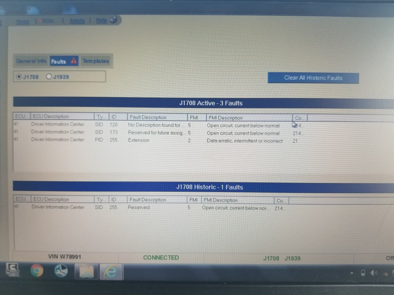
Found the engine ground to the frame disconnected and arcing so cleaned and reattached that but no change. Also pulling the marker light fuse kills power to the gauges.
05 western star gauges schematic
Discussion in 'Heavy Duty Diesel Truck Mechanics Forum' started by Kenllah, May 7, 2021.
Page 1 of 2
-
Attached Files:
Last edited: May 8, 2021
-
-

Trucking Jobs in 30 seconds
Every month 400 people find a job with the help of TruckersReport.


-
Update for anyone needing info.
-
Pins 5 and 6 are the datalink wires. You should never see battery voltage or ground on them. Typically 0.5 to 4.5 volts.
Kenllah Thanks this. -
Deleted
Last edited: May 8, 2021
Reason for edit: Bad info -
Did you not say in your first post that you're seeing 0.7 to 1.X volts on pin 6?
I'm looking at the picture of the plug you labled and then at the schematic. I have a suspicion that you might have mislabled the numbers in the picture. If you re-lable your picture as follows the readings you're seeing make a little more sense:
1 2
3 4
5 6
Can't determine #1 due to schematic being cut off.
#2 would be battery power, matches your readings.
Gets a little goofy here since the pinout numbers on the schematic aren't in line with the others:
#3 could be the ground or backlighting triggered from the headlights/door circuit. Your pinouts labled 2 and 5 in the picture seem to line up with that.
That would make 5 and 6 the datalink wires, which you had labled 3 and 6 in the picture.
This is just me speculating based on the information provided. Unfortunately its not always easy to help diagnose things over the internet. -
I numbered them before I had a schematic. Now I have another photo and have relabeled them but didn't post it yet
-
Spl 4-0 is my problem area.
Attached Files:
-
-
Larger photo
-
Deleted
Last edited: May 8, 2021
Reason for edit: Bad info -
Data star corrections. Pin 1 & 6 should have ignition power from spl-20 fed by fuse f-20. I'll check the fuse in the morning.


Trucking Jobs in 30 seconds
Every month 400 people find a job with the help of TruckersReport.

Page 1 of 2