

Well, I thought all was good when I ended my last thread:
Cobra 29LX and Astatic Road Devil problem
However, I started having problems with the coax shorting out again or grounding issues "antenna warnings". So, I've started all over. I purchased a President McKinley radio and repositioned my Wilson 2000 to the center of the truck (Ford Ranger, not my Mack). Now this is on a fiberglass topper with a new gumdrop mount, but I put a plate of metal under the fiberglass and bonded everything...plate to truck bed to cab and then to the frame and used my ohmmeter to verify proper ground. I also ran my positive from the radio directly to the battery with an inline fuse and grounded the radio chassis as well. So I know that it is well grounded. I've tuned the antenna with initial results of 1.1:1 on ch1 and 1.2:1 on ch40 but it will not stay consistent and I can't receive anyone most of the time and SWR reaching into the high 2's and has spiked upwards to 4 using both the internal and external meters. This all started as you know when I first keyed up that power mic I thought I just had to have on the Cobra 29LX. So I'm thinking it may have fried the antenna or at least caused a short in it considering the fluctuation in readings and it's really the only component I haven't changed. I have ordered another coax (Belden w/Anthenol connectors) and I will also put a new power supply on it. Antenna is next in line...or actually should have been first, opinions? Oh, and just out of curiosity, is this normal (Cobra 29LX not the President) ⬇️
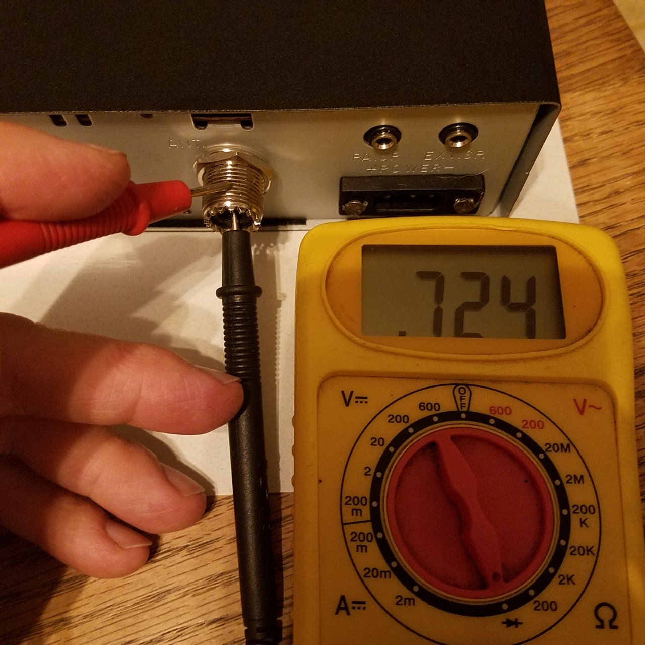
Continuity at radio coax connection
Discussion in 'CB Radio Forum' started by Windmill Hill, Jul 8, 2019.
Page 1 of 2
-
-

Trucking Jobs in 30 seconds
Every month 400 people find a job with the help of TruckersReport.


-
Not sure what you're measuring in the picture. If you had a magnet Mount antenna that was known to be good it would make troubleshooting the radio much easier.
Windmill Hill Thanks this. -
Ok a few thoughts ...
First what you see on the radio is normal, there is a tuning and detection system that shows resistance.
Second is if you are getting fluctuation, the there are only a couple places this happens, the coax if it is shorted or pinched and the vehicle is moving and the other is the antenna ground system, which I am thinking is the problem. A third possilbity is the radio has an issue with the rf ground.Windmill Hill Thanks this. -
Test leads are backwards.But do not understand what it is you think your measuring....Key up the radio see if the meter smokes then you know it was transmitting
Windmill Hill Thanks this. -
I was measuring to see if there was continuity from the center post to the outside of the connector. I knew that there shouldn't be any at those coax points, so I just figured the same for the radio side. Yeah, the leads are backwards but I was measuring ohms...didn't realize that made a difference with the continuity. Still learning and I'm glad that the reading is normal and very grateful for this forum and all the help and patience from such a great group of people
-
Theres going to be something there since your looking into the finals and chokes backwards, not sure what you should actually see, some resistance.
for checking continuity polarity dies not matter. Good LuckWindmill Hill Thanks this. -
Get rid of that gumdrop ant stud bs..Those are garbage...Grab a wilson hd alumium looking stud...
Windmill Hill Thanks this. -
My feeling is that what the DMM is showing is that the battery polarity diode is not (yet) blown into a short. The Vcc (or A+, if you wish) is fed to the collector of the final amp transistor. That big Silicon diode is reverse biased, so it's indicating the junction as intact. If the meter showed ~0v, it would mean either that the protection diode has shorted, or the tech has reversed the polarity with the leads.
So whilst,this my not solve any problems now, it's nice to see the protection stage is still present and doing its job.
Diddly dahdidahLast edited: Jul 12, 2019
Reason for edit: TypoPowder Joints and Windmill Hill Thank this. -
Thank you for that explanation. Good to know all (or most) is good with that particular radio. It's been a great cb and have always had good reports on sound and clarity.
-
Not really, there is a blocking cap between the collector and the tuning circuit. the resistance he is seeing is part of the tuning circuit there is a resistor going to ground before the swr circuit.Windmill Hill Thanks this.


Trucking Jobs in 30 seconds
Every month 400 people find a job with the help of TruckersReport.

Page 1 of 2